
 EN
Key Preparation Principles Before Meter Mounting
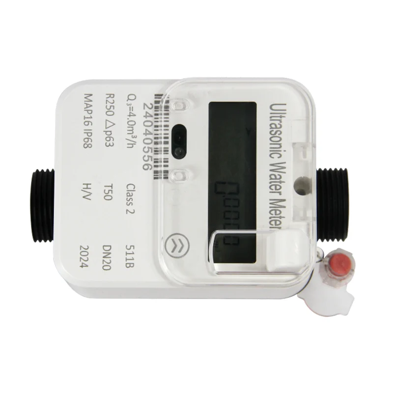
Transitioning from traditional mechanical water meters to modern ultrasonic electronic units fundamentally changes how flow networks operate. Precision sensors and transit-time transducers demand stable hydraulic conditions to deliver peak measurement performance. Field experience shows that most early meter failures or inaccurate readings stem from rushed site evaluation rather than device defects. Assessing line pressure, fluid cleanliness, and ambient temperature parameters before grabbing a wrench avoids costly rework down the line. Pipe stress, stray electrical currents, and uneven pressure spikes can compromise delicate internal components. Isolation valves upstream and downstream must close completely to allow a safe, dry environment during the fitting phase. Inspecting existing pipe walls for inner scale accumulation or severe pitting ensures that mating surfaces will create an airtight, leak-free seal once fully assembled.
Step-by-Step Pipe Flushing and Flange Alignment
Debris, rust flakes, and welding slag remaining inside water lines present immediate risks to any newly installed digital water meter. Flushing the line thoroughly with high-velocity water before positioning the meter body prevents solid particulates from settling inside measurement chambers or blocking ultrasonic sound pathways. Maintaining proper straight pipe lengths is equally vital. A standard rule requires at least ten times the pipe diameter upstream and five times the diameter downstream to smooth out turbulent vortices caused by sharp elbows, reducers, or pumps. Connection flanges or threaded spuds should rest naturally parallel without force fitting. Applying structural strain to pull misaligned pipes together introduces severe housing torque, which distorts internal transducer alignment and compromises long-term IP68 seals. Placing quality rubber gaskets evenly between mating surfaces and tightening mounting bolts in a diagonal sequence using a calibrated torque wrench guarantees uniform compression.
Wiring Protocols and Smart Communication Integration
Modern flow measurement systems rely on solid-state electronics to transmit real-time volumetric data, reverse-flow alerts, and tamper alarms straight to central utility platforms. Connecting signal cables correctly demands strict compliance with wiring diagrams and environmental sealing standards. According to international metering directives such as ISO 4064, protecting signal integrity against external electromagnetic interference is critical for accurate remote automated meter reading. Shielded twisted-pair cabling should be routed away from heavy industrial machinery, high-voltage lines, or frequency converters. When terminating RS485, M-Bus, or pulse output lines inside junction vaults, securing cable glands prevents moisture ingress that degrades circuit boards. For battery-powered wireless models utilizing LoRaWAN or NB-IoT networks, activating internal power jumpers and conducting a preliminary transmission handshake ensures seamless cloud registration before closing pit lids.
Practical System Commissioning and Bubble Removal
Physical mounting represents only half the installation process; thorough commissioning validates operational accuracy inside live pipe networks. Opening main supply valves too rapidly induces severe water hammer, creating shockwaves capable of damaging sensitive internal measuring cells or dislodging elastomeric seals. Upstream valves must be opened gradually, allowing water to fill the meter chamber slowly while air escapes through downstream purge ports. Entrapped air pockets represent a primary cause of signal loss, empty-pipe alarms, or artificial velocity spikes in digital flow devices. Bleeding the line until a clean, bubble-free stream flows ensures full acoustic coupling across ultrasonic transducers. Performing a ten-minute visual leak test under full operating pressure confirms joint integrity, while inspecting the onboard LCD screen confirms steady flow rate readings, battery voltage health, and zero active system error codes.
Diagnostic Insights and Smart Utility Management
Even meticulous installations occasionally encounter field anomalies during initial network integration. Understanding core diagnostic indicators accelerates troubleshooting without unnecessary hardware replacements. For instance, erratic flow readings usually point to severe turbulence from inadequate straight pipe runs or partial blockage in upstream strainers. Zero-flow registration despite active water consumption often indicates reverse physical installation or trapped air pockets around sensor heads. Quick remediation involves verifying directional flow arrows on the meter chassis, bleeding trapped air, and cross-checking baud rates for RS485 communication links. For municipal water suppliers, commercial complexes, and industrial plants seeking long-term operational reliability, partnering with advanced equipment manufacturers makes a decisive difference. ZPMETER engineers precision-driven digital water meters, ultrasonic heat meters, and smart control valves built with robust IP68 protection and dynamic range capabilities up to R400. Leveraging robust OEM manufacturing and global supply chain expertise, ZPMETER empowers utilities worldwide to achieve effortless deployment, reduced non-revenue water loss, and reliable automated metering performance.